Side project — Hardware · Raspberry Pi · Open Source

Slotcar
Laptimer

Two light barriers in the slot, a Raspberry Pi under the table and a live race screen on the iPad. Turning an analog Carrera track into a timed race track — without touching a single car.

Race screen on an iPad: four colour-coded lanes with current, last and fastest lap times, lap counter and start, stop and lap buttons
Race control
"Finally an answer to the oldest question in motorsport: who was actually faster?"
The Problem

"I was faster!"
"No, it was me."

An analog slot car track tells you nothing. No lap times, no lap count, no fastest lap. Just two cars and two people who are both absolutely sure they won.

Carrera Exclusiv and Evolution tracks can be pure analog fun — plug in, race, crash, repeat. What analog racing doesn't do is measure anything.

Digital systems and lap counters exist, but they mean new hardware, chips in the cars or a different track system altogether.

The goal here was simpler: keep the track and the cars exactly as they are, add one modified straight, and let a small computer do the counting. Cheap parts, a cutter knife and an afternoon.
How It Works

Light barrier in.
Lap times out.

01
The car breaks the beam
A 10 mm fork light barrier (f.e. LM393 can be ordered here: LM393 on amazon.de (I get a small commission if you buy via this link)) sits under each slot of one straight. When the car's guide keel passes through the slot, it interrupts the infrared beam.
02
The Pi registers the pass
The sensor's digital output is wired to a GPIO pin. The Raspberry Pi reacts to the edge via interrupt — no polling — and books a lap for that lane.
03
The iPad shows the race
A small Flask web app serves the race screen: start lights, total time and per lane the current, last and fastest lap plus the lap count. Open it in any browser on the local network.
The Build

One straight.
Four steps.

Only one straight gets modified — ideally a short one you can swap in and out. The light barriers are mounted from below, so the driving surface stays untouched and the cars don't notice anything.

Work slowly with the knife: the plastic is thin, and the metal conductor rails right next to the slot must stay intact.

  • 1×Carrera Exclusiv / Evolution straightBoth systems share the same track pieces
  • 2×10 mm fork light barrier, LM393"Photoelectric counter module" for Arduino / Raspberry Pi, I used those: LM393 on amazon.de - if you buy them via the provided link I receive a small commission.
  • 1×Raspberry Pi with 40-pin headerPlus power supply and SD card
  • 6×Female–female jumper wiresLonger ones if the Pi sits off the table
  • —Cutter knife, side cutter, needle-nose pliersThat's the whole workshop
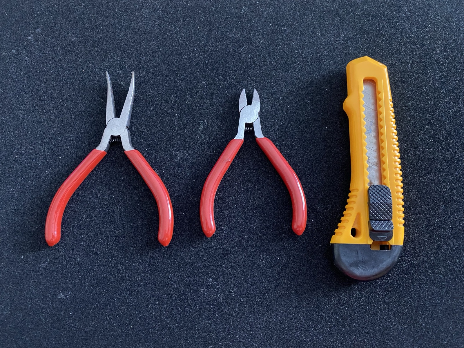
  1. Needle-nose pliers, side cutter and a yellow cutter knife lying on a dark felt mat

    Get the tools ready

    Needle-nose pliers, a side cutter and a sharp cutter knife. Turn the straight upside down on a soft surface so the driving side doesn't get scratched.
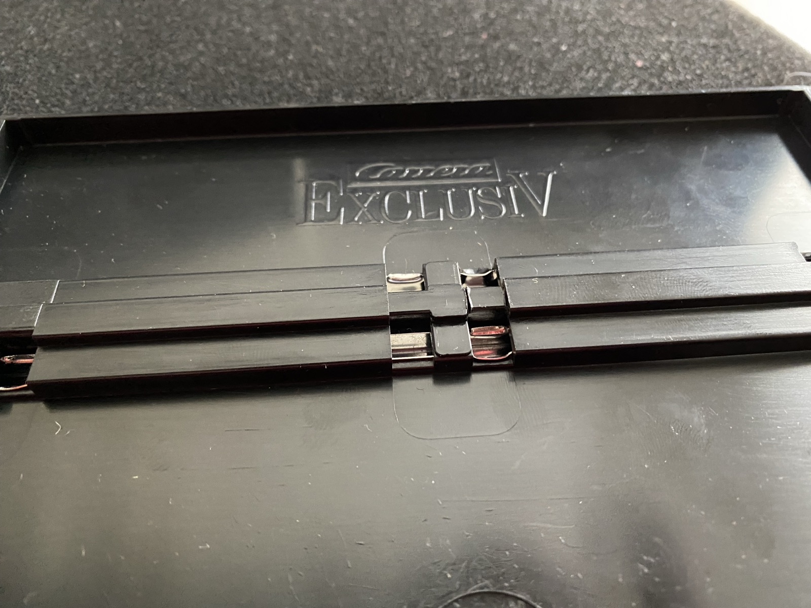
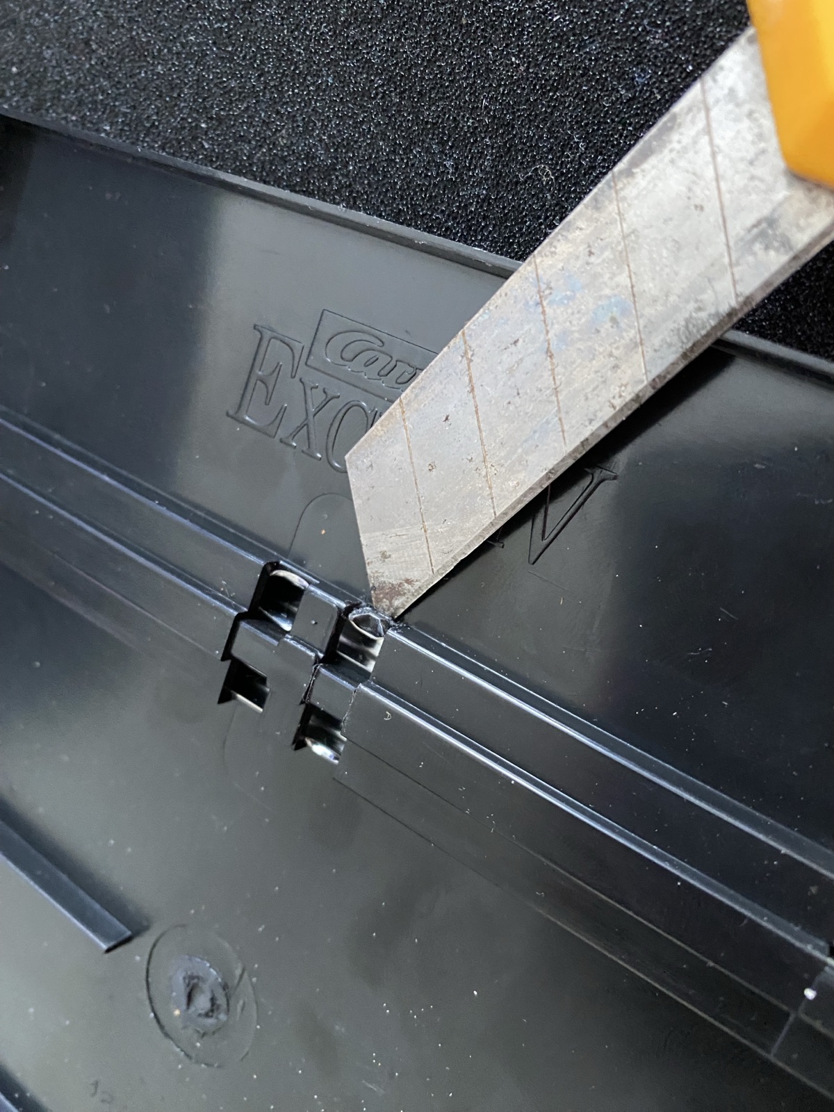
  2. Underside of a Carrera Exclusiv straight, a cutter blade cutting into the plastic next to the slot

    Cut along the slot

    From below, score the plastic right next to the slot ridge — on both sides — where the fork arms of the sensor will sit. Several light cuts beat one hard one.
  3. Underside of the straight with two rectangular openings cut on either side of the slot

    Break out the openings

    Break out the scored pieces with the side cutter and clean up the edges with the pliers. You end up with two small openings, one on each side of the slot.
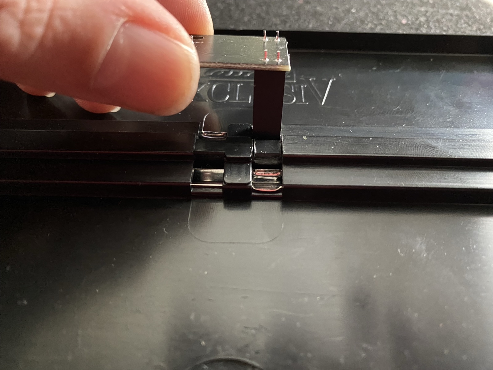
  4. An LM393 fork light barrier being inserted from below into the openings next to the slot

    Insert the light barrier

    Push the fork sensor in from below so its arms straddle the slot. The guide keel now runs right through the 10 mm gap and breaks the beam on every pass. Repeat for the second lane.
Wiring

Twelve wires.
Four lanes.

Each sensor needs power, ground and one signal line. The GPIO pins come straight from lap_timer/config.py in the repo: lane 1 on GPIO18, lane 2 on GPIO23, lane 3 on GPIO24 and lane 4 on GPIO25 (BCM numbering).

Wiring diagram: Raspberry Pi to four LM393 slot sensorsLane 1 sensor: VCC to pin 1 (3.3 V), GND to pin 6, DO to pin 12 (GPIO18). Lane 2 sensor: VCC to pin 17 (3.3 V), GND to pin 14, DO to pin 16 (GPIO23). Lane 3 sensor: VCC to pin 1 (3.3 V), GND to pin 20, DO to pin 18 (GPIO24). Lane 4 sensor: VCC to pin 17 (3.3 V), GND to pin 25, DO to pin 22 (GPIO25).Raspberry PiGPIO · BCM numbering161214161718202225pins 1–26(27–40 unused)Lane 13V3 · pin 1VCCGND · pin 6GNDGPIO18 · pin 12DOLM393slot sensorguide keel10 mm gapLane 23V3 · pin 17VCCGND · pin 14GNDGPIO23 · pin 16DOLM393slot sensorguide keel10 mm gapLane 33V3 · pin 1VCCGND · pin 20GNDGPIO24 · pin 18DOLM393slot sensorguide keel10 mm gapLane 43V3 · pin 17VCCGND · pin 25GNDGPIO25 · pin 22DOLM393slot sensorguide keel10 mm gap3.3 VGroundLap signal (digital out → GPIO input)
Schematic wiring for four lanes. Raspberry Pi header viewed from above, pin 1 top left (square pad). Dashed pads are further GND pins you can use instead.
LaneSensor pinRaspberry Pi pinFunction
Lane 1VCCPin 13.3 V
GNDPin 6Ground
DOPin 12GPIO18 · lap signal
Lane 2VCCPin 173.3 V
GNDPin 14Ground
DOPin 16GPIO23 · lap signal
Lane 3VCCPin 13.3 V (shared)
GNDPin 20Ground
DOPin 18GPIO24 · lap signal
Lane 4VCCPin 173.3 V (shared)
GNDPin 25Ground
DOPin 22GPIO25 · lap signal

3.3 V — not 5 V

The module's digital output follows its supply voltage, and the Pi's GPIOs are not 5 V tolerant. Power the sensors from the 3.3 V pins and the signal stays at a safe level.

AO stays free

Some modules have a fourth pin, AO (analog out). The lap timer only needs the digital output, so leave AO unconnected.

Get the software

Download the latest version from the GitHub releases page, or clone the repository as shown below. New to the Raspberry Pi? Follow the step-by-step setup guide — from flashing the SD card with Raspberry Pi Imager to the first race.

Works for you? Give it a ★ on GitHub — it helps other slot car fans find it.

Run the software

git clone https://github.com/berny-pe/slotcar-laptimer.git
cd slotcar-laptimer
sudo apt install python3-flask python3-rpi.gpio
python3 CarreraLapTimer.py

# then open on the iPad:
# http://<ip-of-your-pi>:5000
The race screen

Live on the
iPad.

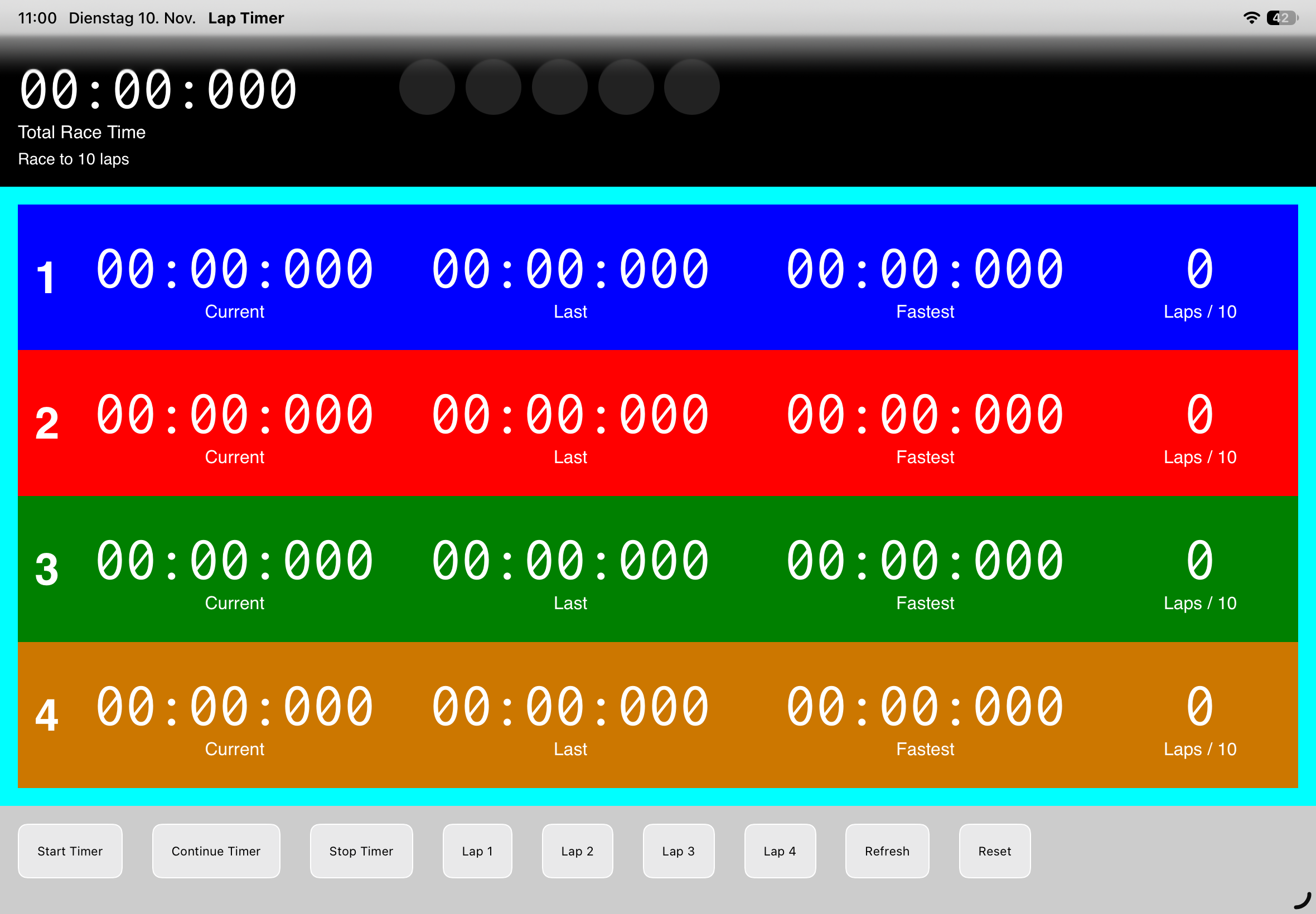
The race screen runs in any browser on the same network as the Pi. Four lanes, current and fastest lap times, and the lap counter, updated as the cars cross the light barriers.

Race screen on an iPad: four colour-coded lanes with current, last and fastest lap times, lap counter and start, stop and lap buttons
Race screen on an iPad, showing the four lanes before the start.
By the Numbers

Small setup.
Big rivalry.

2
Lanes timed in parallel
1/1000
Second display resolution
5
Start lights on the race screen
0
Modifications to the cars
Who Built This

One engineer.
One slot car track.

Bernhard
Engineer · PM · Founder · bernype
PythonFlaskRPi.GPIOHTML/CSS/JSRaspberry PiLM393GitHub Actions

The Slotcar Laptimer is a weekend project — built for races at home, open-sourced because somebody else surely has the same discussions at home.

The software was later refactored: timing logic separated from the GPIO layer, a JSON API for the race controls and unit tests that run on every push — no Raspberry Pi required to test the core.

"Hardware projects have the best bug reports. Usually someone is shouting."
On user feedback

Same principle as the bigger products: solve a real problem with the simplest thing that works, then make it solid.